Patient radiation protection and quality assurance of therapeutic treatment in radiotherapy

Soukaina Bouflous 1, *, Abdellah Halimi 1, Youssef Bouzekraoui 2, Keltoum Dahmni 3
- ISSS Settat, Morocco
- Faculty of Science, Ibn Tofail University in Kenitra, Morocco
- Mohammed V military hospital, Rabat, Morocco
* soukaina1992smp@gmail.com
Abstract: Radiotherapy is an essential modality in the treatment of cancer, combining advanced technology with rigorous medical protocols to ensure optimal therapeutic results. However, it also involves risks inherent to exposure to ionizing radiation, both for the patient and for medical personnel. This article examines the mechanisms and strategies of patient radiation protection and their integration into treatment quality assurance systems. By emphasizing dose management, equipment control and continuous evaluation of procedures, the goal is to minimize risks while ensuring therapeutic effectiveness. A collaborative approach involving medical physicists, oncologists and radiotherapists is also discussed to strengthen the quality of care.
Keywords: Radiation protection in radiotherapy, Quality control, Dosimetry, VMAT, RC3D, TPS.
1. Introduction
Radiotherapy occupies a central place in the treatment of many oncological pathologies, offering an alternative or complement to surgery and chemotherapy. Advances in techniques, such as conformal radiotherapy and image-guided radiotherapy, have improved the precision of treatments, thereby reducing side effects while increasing clinical effectiveness. However, with this increased sophistication comes complex safety and quality challenges.
Radiation protection of the patient constitutes a priority in this context, ensuring that the doses administered are strictly necessary to achieve the therapeutic objectives, while minimizing the exposure of healthy tissues. At the same time, quality assurance, through standardized protocols and continuous assessments, ensures that treatments are carried out with optimal precision and in accordance with best practices.
2. Materials and methods
2.1. Treatment planning system TPS
2.2. TPS-ECLIPSE
Eclipse is an integrated planning ecosystem that combines advanced imaging with precision-driven treatment delivery, enabling clinicians to make the most of radiotherapy’s ability to help eradicate tumors.
2.3. Processing techniques
2.3.1. 3D conformal radiotherapy technique (RC3D)
The aim of conformal radiotherapy or 3-dimensional conformal radiotherapy is to seek the best adaptation of the shape of a high value isodose envelope to the exact shape of the target volume. This technique has developed thanks to the arrival of modern imaging means and multileaf collimator (MLC) technology.
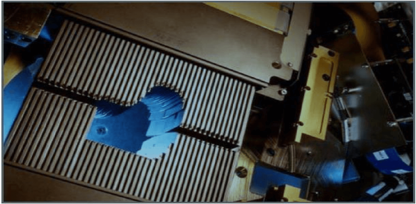
Figure 1: Multileaf collimator
2.3.2. Volumetric Intensity Modulated Arc Therapy (VMAT) technique
VMAT: intensity modulation is obtained by the continuous movement of the blades during irradiation as well as the arm.
This irradiation technique allows the treatment of complex target volumes sometimes enveloping organs at risk. It better protects healthy tissues by only exposing them to minimal doses of irradiation.
It also makes it possible to vary the distribution of the dose within the tumor itself.
2.4. Dosimetric quality control of the Varian linear accelerator
In radiotherapy, it is essential to have precise knowledge of the dose delivered by the line accelerator. To be used clinically
Dosimetric control is done to check whether the dose delivered by the machine is constant. This control is based on the dose rate measurement delivered by the linear accelerator for the different energies of photons and electrons at a reference depth and a maximum depth following the IAEA protocol TRS398. It is divided into two steps:
Step 1: Calibration in water (reference dosimetry). The aim of this step is to check the parameters of the dose profile which are homogeneity, symmetry, penumbra and field size. And even PDD measurement to check beam quality.
Step 2: Calculation of the dose rate using a worksheet prepared by the IAEA. To carry out absolute dosimetry we use the Farmer Chamber Type 30013. We measure the charges stuck in the chamber (Farmer) using OMNI PRO software.
2.4.1. Tools used:
When carrying out our study, measurement tools were used. These tools are:
- The ionization chamber (Farmer Chamber Type 30013)
- The water tank.
- The electrometer.
- The OMNI PRO data acquisition software The ionization chamber:
The ionization chamber makes it possible to measure a charge (ionization). This charge can then be converted to an absolute dose. The ionization chamber consists of an air cavity between two electrodes.
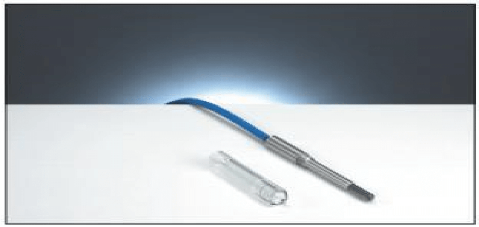
Figure 2: Farmer Chamber Type 30013 ionization chamber
B. The water tank:
The water tank represents one of the important measuring elements in radiotherapy. The measurements that can be carried out are: depth yield, dose profile, absolute dose, etc.
The water tank is made up of three motors and three potentiometers (individual movement) allowing the movement of the ionization chamber in the three planes of space.
The water tank forms a cube with a total capacity of 0.148 m³ (length: 59.4 cm, width: 49.6 cm, depth: 50.25 cm). Installation must be as careful as possible so as not to distort the measurements.
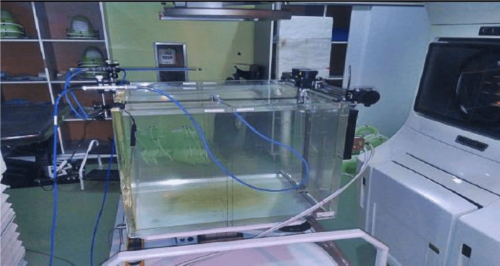
Figure 3: water tank
C. MNI PRO data acquisition software:
This software allows data to be collected after irradiation: depth yield, dose profile and absolute dose.
The movement of the ionization chamber via the movement motors is carried out using this software. After having defined the field size, the energy, the source/water surface distance (SSD, Skin Source distance), we can carry out our measurements. D. The electrometer:
Electrometers are used to measure a charge (nano Coulomb) on the electrodes of the ionization chamber. This charge is then converted into absorbed dose (Gray).
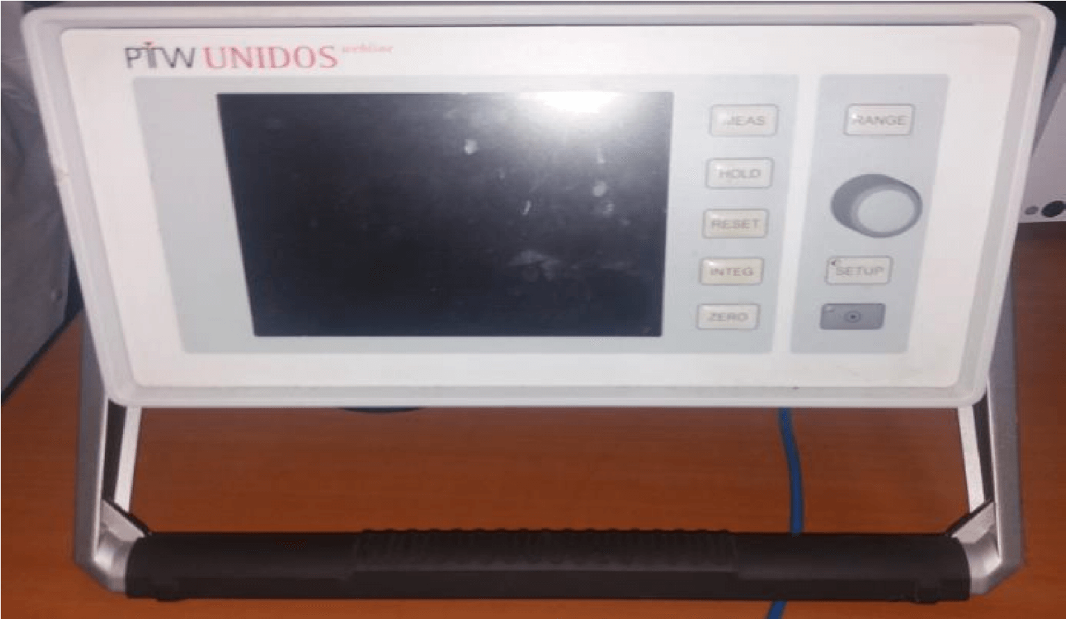
Figure 4: UNIDOS PTW electrometer
E.Thermometer and barometer:
The accuracy of the barometers and the thermometer are used to determine the air density correction factors for absolute dosimetry.
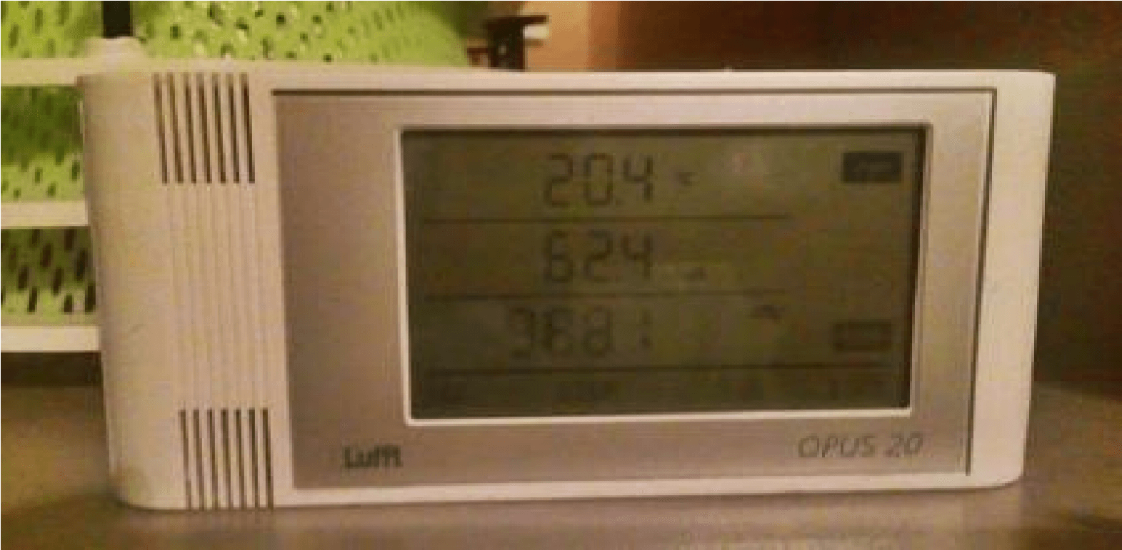
Figure 5: OPUS 20 thermometer and barometer
2.4.2. Calibration in water (reference dosimetry): A. Experimental setup of the water tank:
Installing the water tank is a very important step for data collection. Its installation must be as accurate as possible in order to optimize the precision of the measurements taken. First of all, it is necessary to make the center of the tank coincide with that of the directing beam of the linear accelerator. Simply use the reticle located in the head of the accelerator and superimpose it on the cross at the bottom of the tank. To facilitate installation, it is possible to use repositioning lasers. The tank is then filled with distilled water. The water source/surface distance (SSD) must be set to 100 cm using the telemeter in order to position the ionization chamber at the isocenter of the water tank.
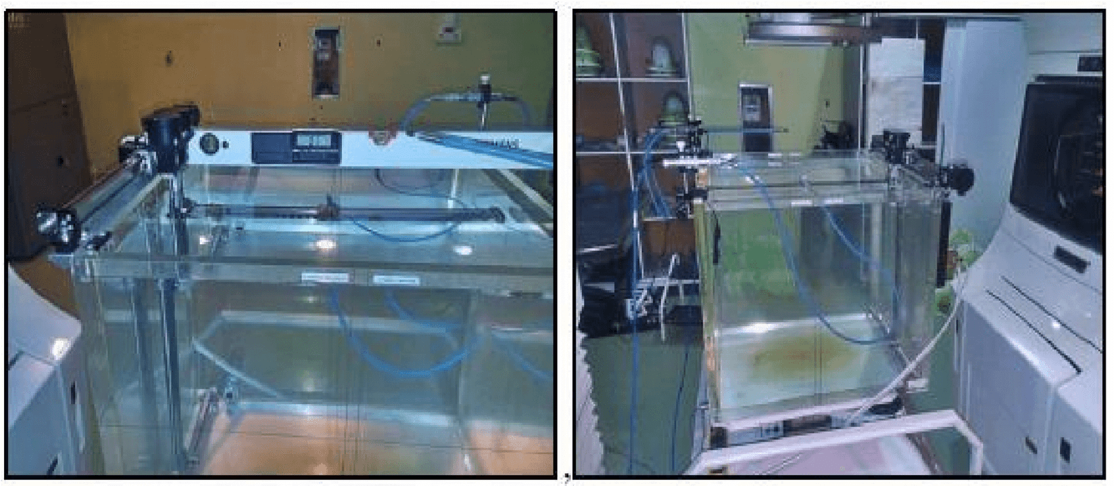
Figure 6: Water tank being assembled
❖ Positioning of the measuring chamber:
For this step we use the Farmer Chamber Type 30013 ionization chamber as a reference and even for the measurement (of PDD and profile). The reference chamber which is used to check the linearity of the MUs is placed on a support above the tank. It must be placed at the edge of the light field. The two chambers are then connected to the TANDEM electrometer, which is itself connected to the OMNI PRO software.
➢ Photons:
✓ Profile measurement:
We can define from the dose profile curve: penumbra, field size, homogeneity and symmetry.
- Symmetry: Typical specifications for symmetry are that any two points, any dose on a beam profile distant from the patient’s central axis, must be less than 2% of each other. The symmetry is then calculated from:
=𝟏𝟎𝟎% ×((𝒂𝒓𝒆𝒂 𝒍𝒆𝒇𝒕+𝒂𝒓𝒆𝒂 𝒓𝒊𝒈𝒉𝒕)/(𝒂𝒓𝒆𝒂 𝒍𝒆𝒇𝒕−𝒂𝒓𝒆𝒂 𝒓𝒊𝒈𝒉𝒕 ))
- flatness: the flatness of the beam F is evaluated by determining the values of the maximum dose points Dmax and minimum Dmin on the beam profile in the 80% of the central part of the beam width, and this is the ratio of:
=𝟏𝟎𝟎%×((𝑫𝒎𝒂𝒙−𝑫𝒎𝒊𝒏)/(𝑫𝒎𝒂𝒙+𝑫𝒎𝒊𝒏 ))
- Field size: For a field size of 10×10 cm2 and a depth of 10cm in water, scans are carried out in the direction of X and Y. From the OMNI PRO system we deduce the size of the irradiation field.
- Penumbra of the irradiation fields: The penumbra is measured for each energy from the dose profiles produced for the study of homogeneity and symmetry. It is characterized by the lateral distance between 80% and 20% of the dose on the axis of the beam, called physical penumbra measured on the main axes of the square fields.
- Procedure :
We set the Farmer Chamber Type 30013 measuring chamber to x=y=0 and to the depth Zref.
We scan the room along the x and y axis and start calculating our profile with the OMNI PRO software which automatically calculates homogeneity and symmetry. The study will cover a field of size 40cm x 40cm:
- Result and discussion:
The chamber being placed at 𝑍𝑟é=5𝑐𝑚, it moves along the two axes x and y, this allows us to obtain the following results
Table: Control of homogeneity, symmetry, Penumbra and field size for photons
| Homogénéité
|
Symétrie
|
pénombre (mm) | la taille de
champ (mm) |
|||
| Energie
|
Mensuel
|
Crossplane
|
Mensuel
|
Crossplane | ||
| 6MEV
|
2,4%
|
3,1%
|
0,4%
|
2,1%
|
1,00
|
1,99
|
| 18 MEV
|
2,3%
|
2,5%
|
0,8%
|
1,9%
|
1,5
|
2,00
|
| Tolérance
|
3%
|
2 %
|
2mm
|
2mm
|
||
| Action
immédiate
|
>3%
|
>2%
|
> 2mm
|
> 2mm
|
||
| Fréquence
|
Mensuel | |||||
Inplane: direction of the chamber in the X axis Crossplane: direction of the room in the Y axis
We also obtain the following dose profile curve:
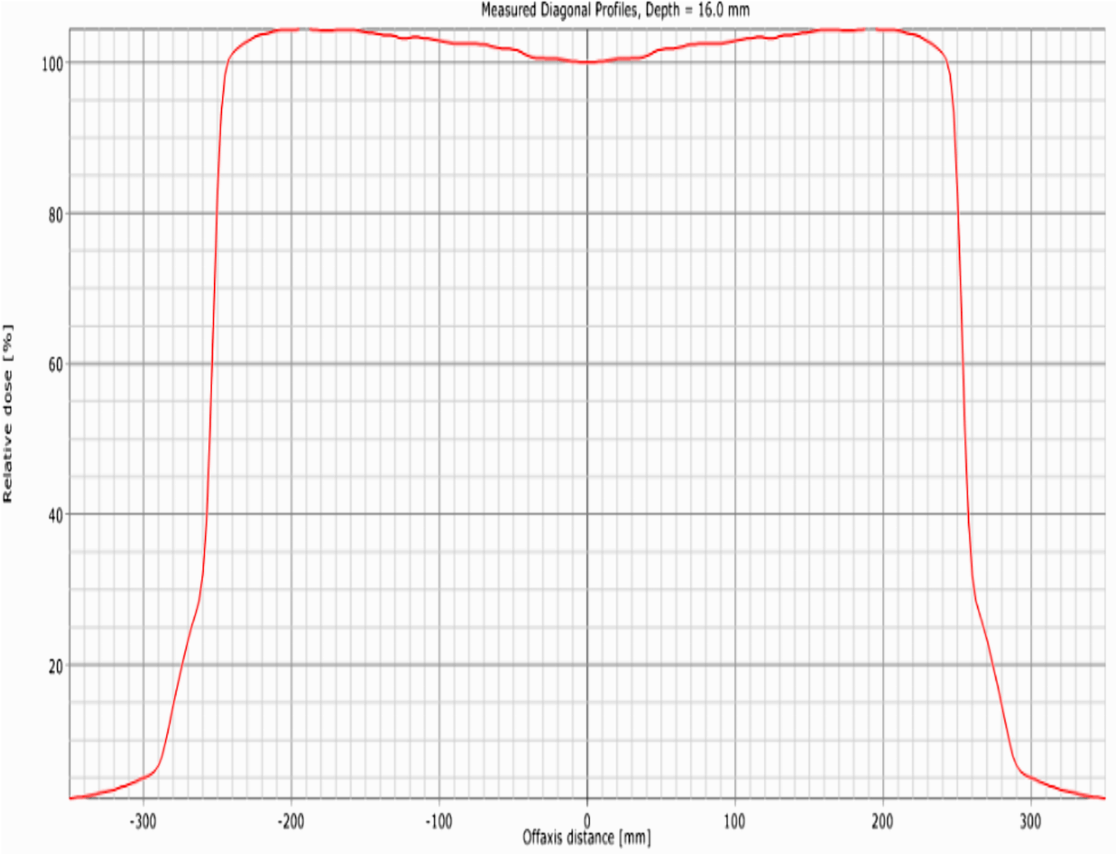
Figure 7: 40X40 field size dose profile for 6MV energy
From the table and the curve we can clearly see that the tolerance of the different examinations was well respected.
✓ PDD measurement: PDD depth performance
The depth yield curves for photons were measured for a field size (20*20) 𝑐𝑚2. They are measured from the surface to a depth of 40 cm for the two photon beams and giving the variation of the absorbed dose as a function of the depth in the water on the axis of the irradiation beam at a source-surface distance of the fixed phantom.
- Procedure :
The Farmer Chamber Type 30013 ionization chamber is swept from 0 to 40 cm in depth. From PDD we output a very important parameter, which characterizes the quality of the beam used, which is the tissue-skin ratio TPR20, 10:
Q= TPR = (1,2661x PDD20, 10) – 0, 0595 With:
PDD = 𝑫𝟐𝟎/𝑫𝟏𝟎
The parameter TPR20, 10 is defined as the ratio of doses on the central beam axis at the depth of 20cm and 10cm in water obtained with a constant detector source distance of 100cm and a field size of 20X20 𝑐𝑚2. The value of TPR20.10 must be between 0.5 and 0.8.
- Result and discussion
By following the previous procedure we obtain the following curves:
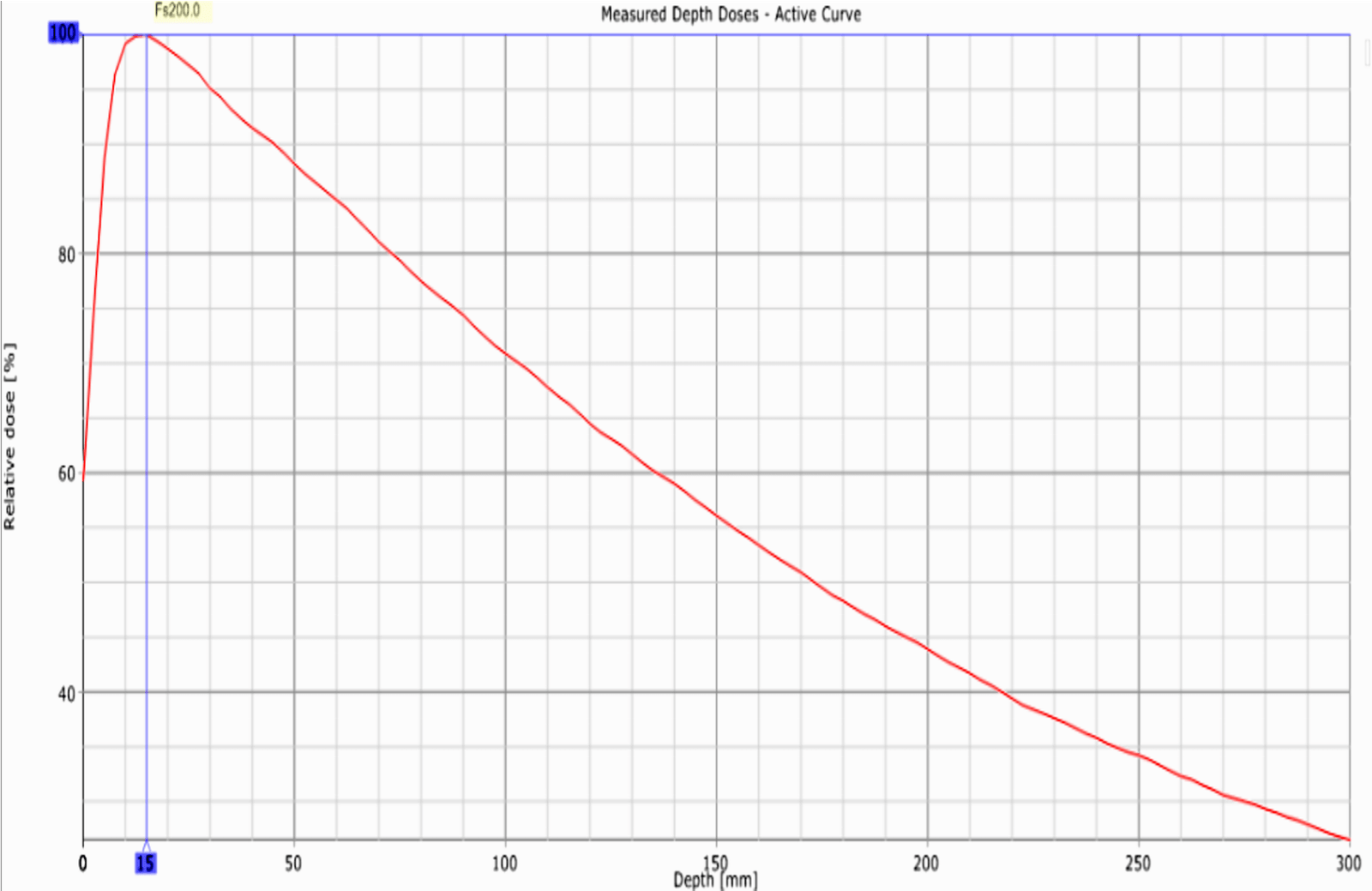
Figure 8: Depth efficiency for the X-ray beam for 6MV energy
As well as the values of TPR20, 10(6MV) and TPR20, 10(18MV) which respect the accepted tolerance:
TPR20, 10(6MV) = 0.681
TPR20, 10(18MV) = 0.772
2.4.3. Routine dosimetry (The Top)
The TOP measurement protocol is identical to that used when measuring the dose under reference conditions: field 10×10 DSP = 100. It makes it possible to control the stability of the dose delivered by the accelerator, that is to say that for a number of monitor units, the accelerator always delivers the same dose (to within 2%) for all the energies of the photons and electrons. This measurement is carried out daily by the DailyQA, each morning we install the DailyQA and we select a 10×10 𝑐𝑚2 field then we check its light projection on the control device which must be exact with the field drawn on the device. Once the field control is validated a green button lights up, otherwise, the button will be red and we will use the woorksheet to recalculate the dose rate so that 100UM is worth a rate of 1cGy /UM.
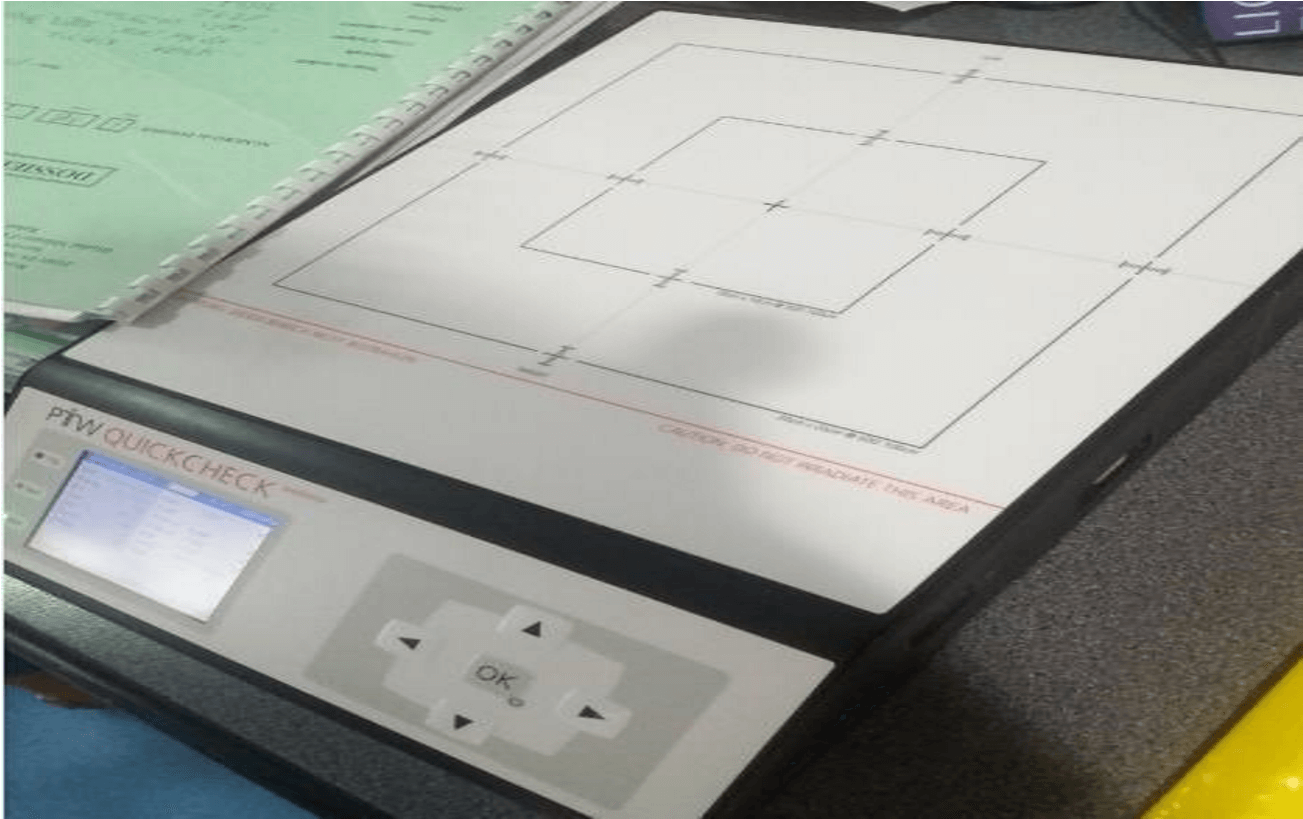
Figure 9: DialyQA device
Conclusion :
According to the results obtained for the quality control of the scanner (image quality), and the mechanical and dosimetric control of the accelerator, we can see that all these tests respect the tolerated standards. No problems to report.
References :
Berkok, H., & Farsi, A. (2009). Determination of the quality of high-energy photon beams used in radiotherapy using different phantoms (Undergraduate thesis, University of Science and Technology – Mohamed Boudiaf, Oran). Medical Physics.
Chauvet, B., & Mazeron, J.-J. (2013). White paper on radiotherapy in France. French Society of Radiotherapy Oncology..
Johnson, T. K. (2007). Commissioning and quality assurance of computerized planning systems for radiation treatment of cancer.
Lafond, C. (2013). Analysis and optimization of the performance of the VMAT technique for its use in radiotherapy (Master’s thesis). University of Rennes 1.
Lake, R., McKenzie, A., Macaulay, E. M., Morgan, H. M., Jordan, T. J., & Powley, S. K. (1999). Physics aspects of quality control in radiotherapy. W. P. M. Mayles (Ed.). Inst. of Physics and Engineering in Medicine.
Mayles, P., Nahum, A., & Rosenwald, J. C. (2007). Handbook of radiotherapy physics: theory and practice. CRC Press.
Podgorsak, E. B. (Ed.). (2005). Radiation oncology physics: A handbook for teachers and students (Chapter 12, p. 407). International Atomic Energy Agency (IAEA).
Disclaimer/Publisher’s Note: The statements, opinions and data contained in all publications are solely those of the individual
author(s) and contributor(s) and not of MJHI and/or the editor(s). MJHI and/or the editor(s) disclaim responsibility for any injury to people or property resulting from any ideas, methods, instructions or products referred to in the content.